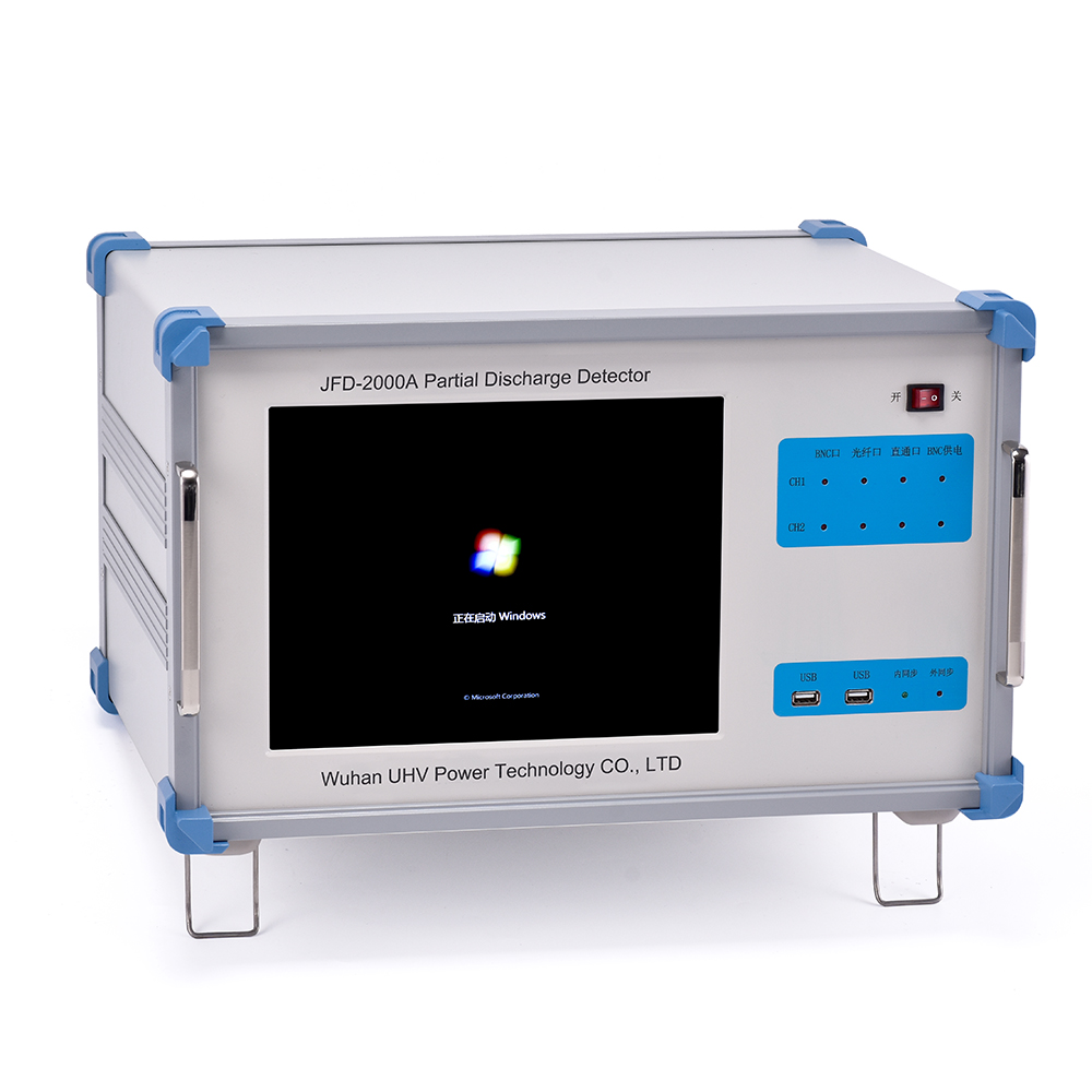
The specialized production of partial discharge testers for UHV power can help many power workers conduct various power tests more conveniently.
Partial discharge test is a non-destructive testing project. From the perspective of testing sequence, it should be placed after all insulation tests. Generally, the power frequency withstand voltage is used as the pre applied voltage for a few seconds, and then reduced to the partial discharge measurement voltage (usually a multiple of Um/√ 3, 1.5 times for transformers, and 1.1 to 1.2 times for transformers), with a duration of a few minutes. Measure partial discharge; Pre applied voltage refers to the overvoltage (such as lightning strikes) during simulated operation. The amount of partial discharge excited by pre applied voltage should not be continued by the partial discharge test voltage, that is, the amount of partial discharge excited when the system experiences overvoltage will not be prolonged by long-term operating voltage
Specific discharge steps:
1. Select the test circuit and determine the connection method between the test power supply and the partial discharge test circuit. It should be carried out in accordance with the national standard GB7354-2003 "Partial Discharge Measurement" and the industry standard DL417-91 "Guidelines for On site Measurement of Partial Discharge in Electrical Equipment".
When selecting a test circuit, reference should be made to the current test power and capacity, as well as the requirements for the test power:
1.1 Voltage Transformer: To prevent excessive excitation current, it is recommended to use a 150Hz or other suitable frequency test power supply for the pre applied voltage of the voltage transformer test. Generally, intermediate frequency power generated by electric generator sets, 150Hz power generated by three-phase power transformer delta connection, or other forms of intermediate frequency power can be used.
When using a magnetic saturation type three frequency generator as a power source, it is easy to cause severe waveform distortion, resulting in the amplitude relationship between the peak value and the true effective value voltage not being a multiple of √ 2, which may cause the actual peak voltage of the primary winding to be too high. High voltage can cause damage to the test product, so a peak voltage meter must be connected to the high voltage side of the test product to monitor the voltage.
The voltage waveform should be close to a sine waveform. When the waveform is distorted, the peak voltage should be divided by √ 2 as the test voltage value.
1.2 Current Transformer: Generally, a test power supply with a frequency of 50Hz can be selected.
1.3 Transformer: Generally, 50Hz harmonics or other suitable frequencies are used. A three-phase transformer can be excited in three phases or in one phase.
2. Determine the allowable level of partial discharge and select standard pulses for calibration. According to DL/T 596-1996 "Test Code for Protection of Power Equipment" and relevant accident prevention technical measures, combined with regional partial discharge standards and industry standards, determine the test samples. Partial discharge allowable level (test standard).
After determining the testing standards, standard pulses can be selected to calibrate the testing circuit. If the allowed partial discharge level is 50PC, 50PC standard pulse can be selected for calibration.
3. Pressure measurement
3.1 Transformer test: The test voltage should be turned on at a voltage not exceeding one-third of the specified measurement voltage, then slowly and evenly raised to the pre applied voltage for 10 seconds, and then lowered to the specified measurement voltage, held for more than 1 minute, and then the discharge amount should be read; Finally, when the voltage drops below one-third of the measured voltage, the power can be cut off.
3.2 Transformer Test: The test voltage should be connected to the power supply at a voltage not exceeding one-third of the specified measurement voltage, and then slowly and uniformly raised to the specified measurement voltage for 5 minutes; Then increase the test voltage to the pre applied voltage and decrease it to the specified level after 5 seconds to measure the voltage. When there is no upward trend within 30 minutes, the voltage can be reduced to less than one-third of the measured voltage and the power can be cut off. For transformers with unstable partial discharge to be tested, the measurement time should be extended until the partial discharge is stable and does not endanger the safety of the transformer. For transformers with local amplification,
Initial discharge voltage: The voltage slowly and uniformly increases from a low value until the discharge amount just exceeds the specified value for partial discharge. At this point, the applied voltage is the initial discharge voltage.
Extinguish discharge voltage: When the voltage rises above the initial discharge voltage (usually 10% high), the voltage slowly and uniformly decreases until the discharge amount is just below the specified value for partial discharge. At this point, the applied voltage is the extinguishing discharge voltage.
4. Observation of partial discharge. When reading the apparent discharge value, the apparent discharge amount should be calculated based on the highest pulse signal that is repeatedly stable. The true PD signal has a certain degree of symmetry and periodicity, and occasionally higher pulses can be ignored.
The background noise level of the measurement circuit should be less than 50% of the allowable discharge level. When the allowable discharge level of the tested product is 10PC or below, the background noise level can reach 100% of the allowable discharge level.
Partial discharge refers to the non penetrating discharge that occurs between the electrodes of the insulating medium in high-voltage electrical appliances under the action of high electric field strength. The purpose of testing is to discover defects in the equipment structure and manufacturing process. For example, the local electric field strength in insulation is too high; Metal parts have sharp corners; Insulation mixed with impurities or defective products. The poor electrical connection between the metal grounding part and the conductor can eliminate these defects and prevent partial discharge damage caused by insulation.


