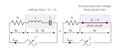
At resonance, the impedance of the inductor is equal to the impedance of the capacitor
Therefore, ωL= 1 /ωC, Where w is angular frequency=2 π f
ω 2 LC = 1
ω 2 = 1 / LC
Therefore, during resonance, the impedance of the RLC circuit is equal to R
Due to the fact that the current flowing through a series resonant circuit is the product of voltage and impedance, the impedance Z is at its minimum value (=R) during resonance. Therefore, the circuit current at this frequency will reach its maximum V/R value, as shown below.
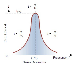
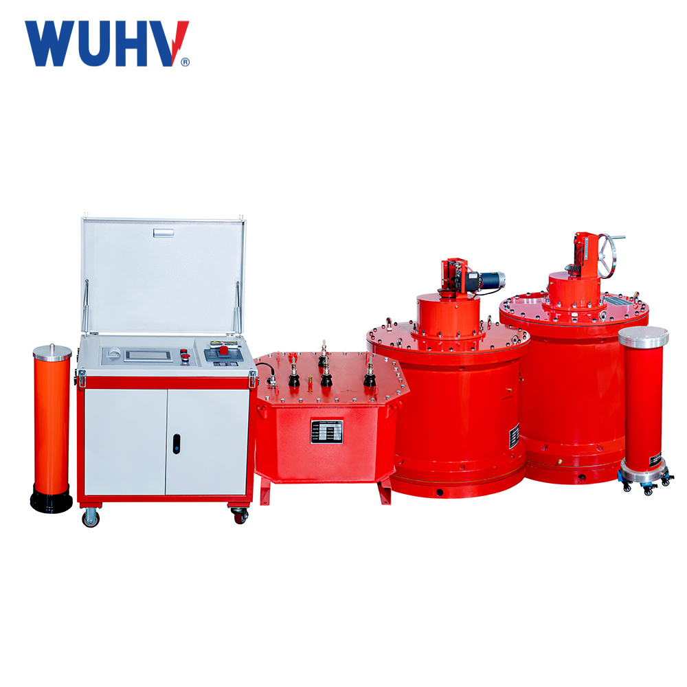
The frequency response curve of a series resonant (also known as a power frequency withstand voltage test equipment) circuit indicates that the magnitude of the current is a function of frequency. When plotted on a graph, it can be seen that the response starts from near zero, reaches its maximum value at the resonant frequency when I MAX=IR, and then decreases again to near zero as ƒ becomes infinite. The result is that even during resonance, the amplitude of the voltage C across the inductor L and capacitor C can be many times greater than the power supply voltage because they are equal and cancel each other out when they are opposite.
Due to the fact that a series resonant circuit only operates at the resonant frequency, this type of circuit is called a receiver circuit because at resonance, the impedance of the circuit is at its minimum value, making it easy to accept a current with a frequency equal to its resonant frequency.
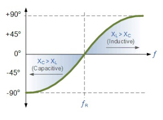
It should be noted that since the maximum current flowing through the circuit during resonance is only limited by the resistance value, the power supply voltage and circuit current must be in phase with each other at that frequency. Then, the phase angle between the voltage and current of the series resonant circuit is also a function of the frequency of the fixed power supply voltage, and is zero at the resonant frequency point when V, I, and VR are in phase with each other, as shown below. Therefore, if the phase angle is zero, the power factor must be 1.
