The insulation structure of electrical equipment can withstand the following four voltages during operation:
1. The insulation structure of electrical equipment must be able to withstand the maximum working voltage of the power frequency for a long time throughout the entire operation process. Usually referred to as the maximum operating voltage of the system, it is usually 1.15 times the rated voltage.
2. Transient overvoltage, including rising frequency voltage and resonant overvoltage, is caused by the capacitance effect, load shedding, and asymmetric grounding of the no-load line in the resonant AC power frequency voltage of the series resonance test device. When the load suddenly unloads, due to the fact that there is only one unloaded transmission line in the power supply, and the grounding reactance of the transmission line can be represented by X0, the current flowing through the internal resistance of the power supply becomes a capacitive current. This current flows through the reactance in the system, causing the voltage to rise. Because the boost is nearly 50Hz AC voltage, the power frequency voltage rises. Under the current function of relay protection, its action time is about tens of milliseconds to one second. With the long-term application of AC voltage, it has a significant impact on the insulation aging of electrical equipment and the insulation structure of power systems. Resonant overvoltage is caused by resonance caused by ferromagnetic effects or nonlinear inductive elements of iron cores, with higher amplitude and longer duration, and its frequency can be the fundamental or higher-order harmonic of the power frequency.
3. Overvoltage operation is caused by the operation of circuit breakers in the power system, in a series resonant circuit composed of resistors, inductors, and capacitors. When the capacitance XC and inductance XL are equal, the phase of the voltage U and current I in XC=XL is the same, and the circuit is resistive. This phenomenon is called series resonance. When a circuit series resonant circuit is used, such as cutting off or closing a long no-load line, cutting off an no-load transformer (pneumatic variable), etc., the overvoltage waveform is very irregular and the situation varies greatly. It can be an attenuated oscillation wave or a non periodic voltage shock wave, generally reaching the maximum voltage within 1ms. The overvoltage during power system operation is related to the system voltage. The higher the system voltage, the lower the voltage. The voltage of a 6-35 kV system is about 5-4 times that of a 6-35 kV system.
4. Lightning overvoltage often causes insulation damage to electrical equipment. In order to ensure the safe operation of the power system, lightning protection measures must be taken. Such as installing lightning rods, lightning arresters, etc.
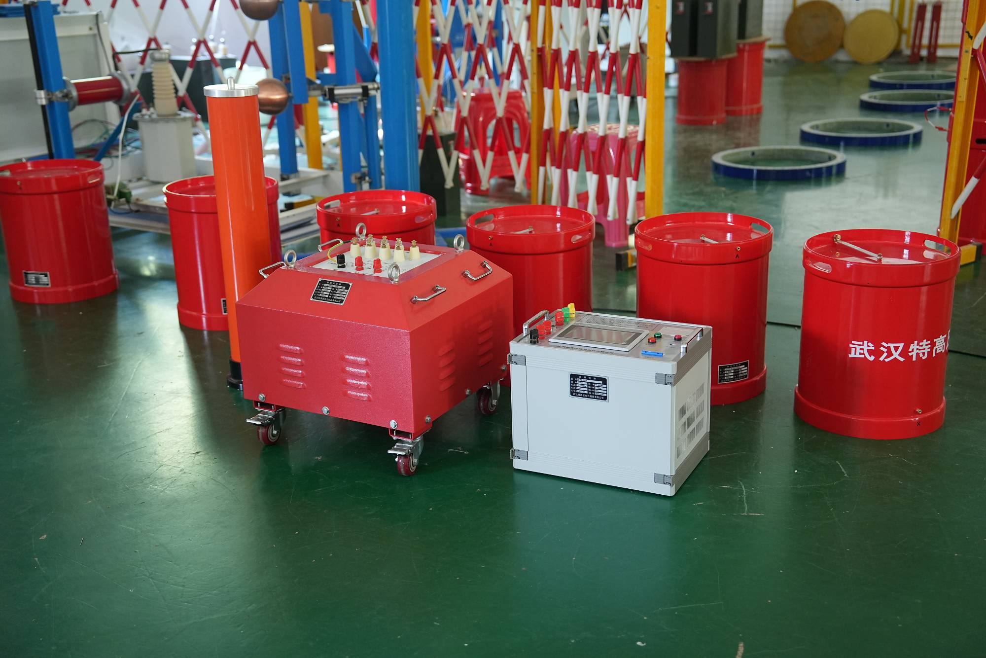
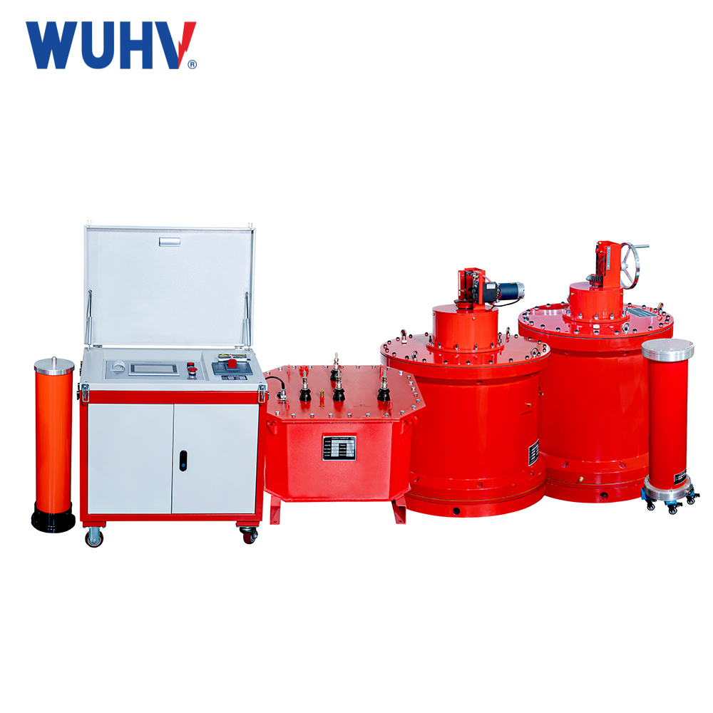
In order to ensure that the insulation structure can withstand the above four voltages, it is necessary to conduct shock wave voltage tests and power frequency voltage resistance tests on the insulation structure. The insulation structure must have sufficient margin, and the capacitors of the sample and reactor form a series resonant connection mode. The voltage divider is connected in parallel to the tested object to measure the resonant voltage of the test object and serve as an overvoltage protection signal.


